Welcome to Handiham World.
You can do it!
Today we are going to begin with Troubleshooting 101 as part of our initiative to help new ham radio operators (and even some of us older ones) learn how to do some basic troubleshooting for ourselves. Yes, it can be tempting to ask someone else to do things for us. This can become a bad habit when it keeps us from learning new things, especially things that we could - with a bit of practice - learn to do for ourselves. Knowing these basic things can serve us well in the future when no help is available. This next simple exercise is one that we will be practicing at this summer's Radio Camp. You can do it yourself once you learn a few basics.
Troubleshooting 101

Checking continuity
There is no doubt in my mind that having a simple way of checking continuity is one of the troubleshooting basics. Continuity, as we talk about it here, means that a path supporting electrical current flow exists between two or more conductors. That is not to say that a current is actually flowing - it just means that if and when we want a current to flow, it can do so.
Let's take the example of a piece of coaxial cable. At Handiham headquarters we have lots of long and short coaxial cables. Some are jumper cables that are typically used to connect radios with accessories, such as a transceiver to antenna tuner or SWR meter, or maybe both with a couple of short coaxial jumpers. Then there are the longer runs of coaxial cable that carry the signal out through the wall to a lightning arrestor and then to the antenna, depending on the installation. The proper operation of the station depends on conductivity between the radio and the accessories and antenna. Each link in the chain represents a possible failure point.
If I pull a coaxial cable jumper out of the junk box at Handiham headquarters, I always take a moment to check it out for continuity. Knowing that donated coaxial jumper cables have come in from a wide variety of sources, I know better than to trust that they will be good! There are two steps to checking a cable. The first is to see if the center conductor is soldered into the center pin on each connector. Then unscrew the outer part of the PL-259 plug so that you can see if the coax braid has been properly soldered. If the coax braid is not properly soldered, loose strands may be poking out of the solder holes or the solder may be lumpy and not properly flowed into the holes and onto the body of the connector. It's usually pretty easy to tell if there is a problem connector if the PL-259 plug moves freely when you twist it while holding onto the cable itself. A loose plug means that you should set that jumper aside for repair.
The second test is for continuity. Even if a coaxial jumper looks perfect and the PL-259 connectors are solid, the cable may still be bad. The possible conditions that may be revealed by your continuity test are these five:
- The cable is good and ready for use.
- The cable is open through the outer shield.
- The cable is open through the center conductor.
- The center conductor is shorted to the shield.
- An intermittent condition exists that causes a short or open when the cable is flexed.
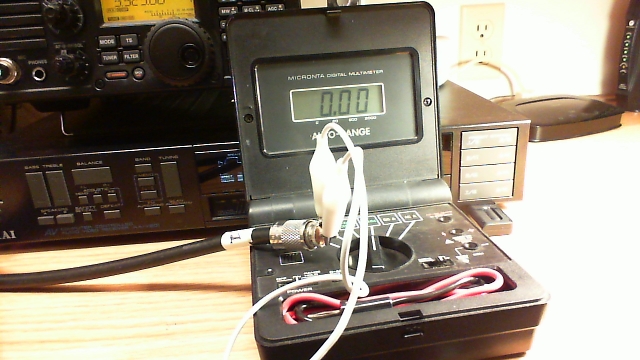
Photo: Simple test gear for a continuity check includes a clip lead and a multimeter with a continuity buzzer.
Your test gear is pretty basic. You need a simple continuity checker, which could light a lamp or sound a tone when the connection is made. Some multimeters have a continuity setting that sounds a tone, but you can also just use the resistance setting. While resistance is not the same as continuity, the idea is to test for extremely low resistance, which indicates that there is a connection between conductors. If you have a multimeter with a continuity setting, use that. If your meter only has a selection of resistance ranges, just start with R times 100. Touch the meter probes together to either hear the continuity tone or watch the meter reading. If you are watching the meter display it should indicate very low or no resistance when the probes are touched together.
The other thing you need is a clip lead with alligator clips on each end. Depending on your dexterity and the length of the cable to be checked, this little clip lead can prove very handy indeed.
Now we are ready to do the testing. Be sure you are working only with completely disconnected coax. Both ends must be free.
- Take one end of the disconnected coax. Remember, we are NOT able to test continuity with the coax connected to any equipment or antennas. Touch one multimeter lead to the center pin of the PL-259 plug and the other to the outer metal part of the plug. You should hear nothing, indicating that the cable is not shorted. This is always the first test, because we must eliminate the possibility of shorts before we can make any assumptions about the center conductors or the shield.
- Next, take the clip lead and use it to short the coax at one end by connecting the center pin of one of the PL-259 connectors (it doesn't matter which one) to the shield side of that same connector. Take the free end of the coax and touch one multimeter probe to the center pin and the other to the metal shield of that PL-259. You should now hear the buzzer that indicates continuity.
- You have now completed the basic tests, because you have determined that the cable is not shorted and by passing a current through the entire length of the center conductor and back through the shield, you have determined that both the center conductor and shield are intact. The final test is to flex the cable and wiggle the connectors while performing both of these tests again. If it helps, you can add two additional clip leads to connect the multimeter probes so that you don't have to try to hold them in contact with the PL connectors. This will help determine if the cable is intermittent.
- If the cable fails any of the tests, feel free to test the shield to shield and center pin to center pin connections separately. Never use a cable that is suspect, because it could cause damage to your equipment.
- Last but not to be missed is a final check along the length of the cable for any obvious bad spots, such as a break in the outer jacket or any suspicious bends or bumps in the cable.
If you are testing a long length of coax that goes through a wall, you will still need access to both free ends with the connectors. In this case, you are going to have to do some legwork, so if you are starting outdoors, clip the clip lead onto the PL-259, shorting the center pin to the shield. Go back indoors with the multimeter and check across the inside PL-259, where you should get the sound of the continuity buzzer. Grab the multimeter and head back outdoors, then remove the outdoor clip lead and take a reading across the PL-259, center pin to shield. There should be no continuity. This is about the easiest way to check a long feedline.
Email me at handiham@couragecenter.org with your questions & comments.
Patrick Tice
Handiham Manager
Patrick Tice
Handiham Manager